
3D Scan to CAD Conversion Service with Parametric Modeling (Reconstruction)
3D Scan to CAD conversion transforms raw scan data into precise, editable engineering models that drive modern manufacturing and design workflows. When you capture a physical object using 3D laser scanners, you get point clouds or mesh files—but these formats don’t give you the parametric intelligence needed for engineering modifications, simulations, or production documentation.
Industries ranging from aerospace to automotive rely on 3D Scan to CAD Conversion Service with Parametric Modeling (Reconstruction) to bridge this gap. The process converts mesh data into fully functional CAD models complete with dimensions, constraints, and feature history. You can then modify these models, generate technical drawings, and integrate them into your existing design workflows.
This article explores how parametric reconstruction works, what deliverables you can expect, and the specific advantages and challenges you’ll encounter when choosing this approach for your projects.

Understanding the Basics of 3D Scanning and CAD Modeling
3D scanning technology captures the physical shape of real-world objects using devices like laser scanners, structured light systems, or photogrammetry methods. These devices measure thousands to millions of points on an object’s surface, creating point clouds that represent the exact shape and size of the scanned item. The scanner essentially creates a digital version by recording spatial coordinates, which are then compiled into mesh files—typically in formats like STL, OBJ, or PLY.
The raw output from 3D scanners consists of triangulated mesh data. While these meshes provide visual accuracy, they lack the intelligent design information needed for engineering applications. You can’t easily modify dimensions, extract manufacturing specifications, or perform simulations with mesh files alone.
CAD modeling solves this problem by creating structured, mathematically-defined shapes. CAD software uses precise curves, surfaces, and solid bodies defined by parameters, constraints, and relationships. This structured approach enables you to generate technical drawings, perform tolerance analysis, and integrate models into manufacturing workflows.
Reverse engineering connects scanned mesh data with functional CAD models. This process involves analyzing the scan data to understand the original design intent and then reconstructing the shape using CAD tools. You’re essentially working backward from the physical object to create an editable digital model that preserves size accuracy while adding the flexible intelligence required for modern design and manufacturing processes.
The Process of Parametric Reconstruction from 3D Scans
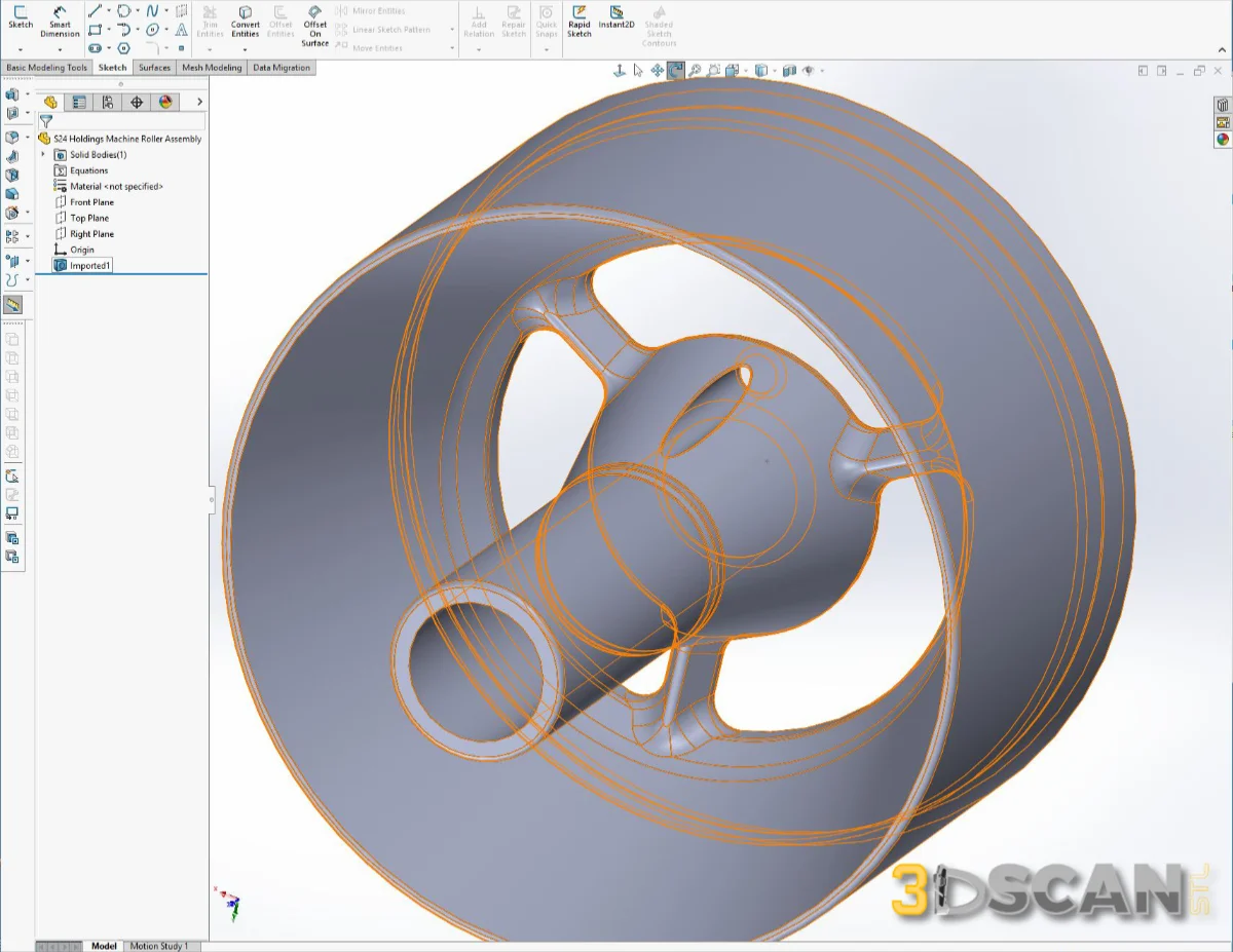
Parametric reconstruction transforms raw scan data into intelligent CAD models through a systematic workflow that prioritizes geometry capture and precision. The process begins with importing your mesh file—typically an STL or OBJ format—into specialized CAD software where it serves as a reference backdrop for the reconstruction work.
The reconstruction workflow follows these essential steps:
-
- Mesh Preparation and Analysis: The scan data undergoes cleaning to remove noise, fill holes, and smooth irregularities that could compromise accuracy.
-
- Feature Identification: Key geometric features like planes, cylinders, holes, and edges are identified and measured directly from the scan.
-
- Parametric Sketch Creation: 2D sketches are drawn using the identified dimensions and constraints, establishing the foundation for 3D features.
-
- Feature Building: Extrusions, revolves, sweeps, and other parametric operations are applied to construct the 3D geometry with full editability.
-
- Constraint Application: Dimensional and geometric constraints are added to maintain design intent and enable future modifications.
Optimization techniques play a critical role throughout this process. You’ll find that skilled technicians continuously perform deviation analysis, comparing the reconstructed CAD model against the original scan to maintain tolerances between 0 and 0.25 mm. This involves strategically simplifying complex geometries where appropriate while preserving critical dimensions and functional surfaces.
The parametric approach also includes supplementing incomplete scan areas through geometric inference—using symmetry, pattern recognition, and engineering judgment to fill gaps logically. This creates a complete, manufacturable model rather than a literal copy of potentially damaged or worn parts. Each feature added to the history tree maintains its independence, allowing you to modify individual elements without rebuilding the entire model.
Deliverables and Data Formats Offered in Our Service
When you engage our 3D Scan to CAD Conversion Service with Parametric Modeling (Reconstruction), you receive carefully prepared deliverables designed to integrate seamlessly into your workflow. The standard output format is STEP format (typically .STEP or .STP files), which provides universal compatibility across virtually all major CAD platforms. This format preserves the geometric integrity of your reconstructed model while ensuring you can open and work with the files regardless of your preferred CAD software.
You also have the option to request files in your native CAD format—whether that’s SolidWorks, CATIA, Inventor, or another platform. These native files come with complete feature history, giving you access to the entire parametric tree of features, constraints, and dimensions used during reconstruction. This feature history transforms the model from a static geometry into a living, editable design.
The inclusion of feature history is what sets parametric reconstruction apart from simple surface modeling. You gain the ability to:
-
- Modify individual features without rebuilding the entire model
-
- Adjust dimensions and see changes propagate through dependent features
-
- Add new features that reference existing geometry
-
- Create design variations efficiently
-
- Generate accurate technical drawings with proper dimensioning
This editability proves invaluable when you need to adapt legacy parts, create manufacturing variations, or continue design development from the scanned baseline.
Advantages and Challenges of Using Parametric Modeling in 3D Scan to CAD Conversion
Parametric modeling brings substantial benefits to your 3D scan conversion projects. You get editable models that allow you to modify dimensions, features, and constraints without rebuilding the entire geometry from scratch. This editability means you can adjust hole diameters, change fillet radii, or alter mounting positions with simple parameter changes rather than manual remodeling.
The small file size advantage becomes apparent when you compare parametric CAD files to their mesh counterparts. A typical STL mesh file containing millions of triangles might occupy hundreds of megabytes, while the same part reconstructed parametrically could be just a few megabytes. This compact size simplifies file sharing, reduces storage costs, and speeds up loading times in your CAD software.
You also gain the ability to generate technical drawings directly from parametric models, complete with dimensions and annotations. The feature history tree lets you understand how the part was constructed, making it easier for your team members to comprehend the design intent and make informed modifications.
The challenges emerge when you’re dealing with complex organic shapes like sculpted surfaces, ergonomic handles, or artistic components. Parametric modeling relies on geometric primitives and mathematical definitions, which struggle to accurately represent freeform surfaces. You might find that organic geometries require excessive features to approximate the scanned shape, potentially negating the file size benefits. In these scenarios, surface modeling or hybrid approaches often deliver better accuracy and more manageable models.
Tools, Software, and Quality Assurance Measures in Parametric Reconstruction
The success of parametric reconstruction relies heavily on the right combination of software tools and rigorous quality control processes. FreeCAD stands out as a popular open-source option that supports parametric modeling workflows, offering a cost-effective solution for converting 3D scans into editable CAD models. You’ll find that professional services also utilize industry-standard platforms like SolidWorks, CATIA, and Siemens NX, each bringing specialized capabilities to handle different reconstruction complexities.
The software selection depends on your project requirements—some tools excel at handling mechanical components with precise geometric features, while others provide better support for more intricate surface reconstructions. Professional conversion services typically maintain proficiency across multiple CAD platforms to accommodate client preferences and ensure native file compatibility.
Quality assurance forms the backbone of reliable parametric reconstruction. Deviation analysis serves as the primary verification method, comparing the reconstructed CAD model against the original scan data to measure accuracy. You can expect professional services to generate detailed color-coded deviation maps that highlight discrepancies, typically maintaining tolerances between 0 and 0.25 mm.
The analysis process involves:
-
- Aligning the CAD model with the reference scan data
-
- Calculating point-to-surface distances across the entire geometry
-
- Identifying areas that exceed acceptable tolerance thresholds
-
- Iteratively refining the model to minimize deviations
This systematic approach guarantees that your final CAD model maintains dimensional integrity while preserving the parametric features necessary for downstream modifications.
Get Started with Our Tailored 3D Scan to CAD Conversion Solutions Today!
You deserve a 3D Scan STL to CAD Conversion Service with Parametric Modeling (Reconstruction) that understands your unique project requirements. Whether you’re working with legacy parts, need precise reverse engineering, or require editable CAD models for manufacturing, our team is ready to help.
Reach out to discuss your specific scanning data, desired accuracy levels, and preferred CAD formats. Our customer support team provides personalized assistance throughout the conversion process, ensuring you receive exactly what your project demands.
We believe in ongoing collaboration with you—from initial consultation through final delivery and beyond. Contact us today to transform your 3D scan data into fully parametric, editable CAD models that drive your design and manufacturing goals forward.
Frequently Asked Questions
What is 3D Scan to CAD conversion with parametric modeling, and why is it important?
3D Scan STL to CAD conversion with parametric modeling involves transforming accurate 3D scan data of physical objects into editable CAD models using parametric reconstruction techniques. This process is significant across various industries as it enables precise digital representation, facilitates design modifications, and supports reverse engineering efforts.
How does parametric reconstruction work in converting 3D scans to CAD models?
Parametric reconstruction uses 3D scan data as a reference to create geometry-capturing, editable CAD models. The process includes optimization techniques to ensure high-quality results, producing models that maintain feature history for easy future edits and design changes.
What file formats are provided after the 3D Scan to CAD conversion service?
Our service delivers standard file formats such as STEP files for broad compatibility and native CAD files that include feature history upon request. Including feature history is crucial as it allows clients to make further design modifications efficiently.
What are the advantages and challenges of using parametric modeling in 3D Scan to CAD conversion?
Advantages of parametric modeling include producing fully editable models with smaller file sizes, enhancing workflow efficiency. However, challenges arise when dealing with complex organic shapes where parametric methods may face limitations in accurately capturing intricate details.
What should clients expect regarding accuracy and inputs when using our 3D Scan STL to CAD conversion service?
Clients can expect high accuracy from our reverse engineering approach using parametric modeling. Successful conversions require clear client inputs such as detailed project specifications and quality scan data. Our team provides ongoing customer support to facilitate collaboration throughout the project.