
Converting 3D Scans to CAD Solid Surface Models
 Have you ever held a physical part in your hands and wondered how to turn it into a digital CAD model without starting from scratch? That’s where the ability to convert 3D scans to CAD solid surface models becomes a game-changer for modern manufacturing and design workflows.
3D scan to CAD conversion takes raw scan data—like triangle meshes and point clouds—and turns it into fully editable, manufacturable solid surface models that you can use in any CAD software. This process is a key part of reverse engineering, allowing you to capture existing parts, legacy components, or prototypes and bring them into your digital design environment with accuracy.
This technology connects the physical and digital worlds. You can measure worn parts for replacement, check as-built conditions against design intent, or create CAD documentation for components that never had digital records.
In this article, you’ll learn about the conversion process itself, the benefits it brings to your workflow, and the different methods available for transforming scans into usable CAD models. You’ll discover how to achieve watertight solid models with minimal deviation from the original scanned geometry.
Understanding 3D Scan to CAD Conversion
3D scanning captures the physical geometry of real-world objects and converts them into digital representations. When you scan a part, the scanner collects thousands or millions of data points from the object’s surface, creating either a point cloud or a mesh file. The most common output format is STL (Standard Tessellation Language), which represents the scanned geometry as a collection of connected triangles. You’ll also encounter other formats like OBJ, PLY, or PTX files, but these are essentially non-editable triangle meshes or scattered point data.
CAD solid surface models represent a completely different type of digital geometry. Unlike mesh files, these models consist of mathematically defined surfaces and solids that you can edit, dimension, and use directly in manufacturing processes. The industry-standard format for these models is STEP (Standard for the Exchange of Product Data), which preserves the precise mathematical definitions of surfaces and enables seamless transfer between different CAD systems.
The bridge between raw scan data and usable CAD models is surface reconstruction. This process involves analyzing the mesh or point cloud data and rebuilding it into clean, mathematically defined surfaces. NURBS surfaces (Non-Uniform Rational B-Splines) serve as the foundation for this reconstruction because they can accurately represent both simple geometric shapes and complex freeform surfaces found in scanned parts.
CAD modeling through surface reconstruction transforms those millions of triangles into a manageable set of NURBS surfaces that capture the original geometry with precision. You can think of it as translating a rough sketch into a technical drawing—the information is there, but the format changes to something you can actually work with in professional design and manufacturing environments.
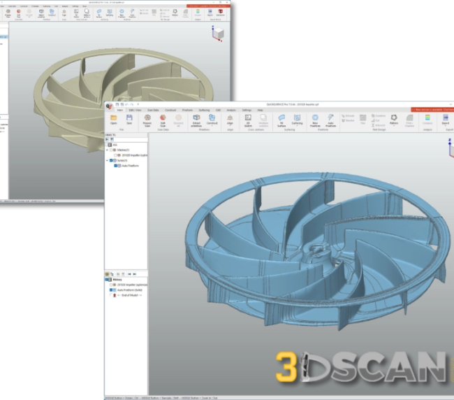
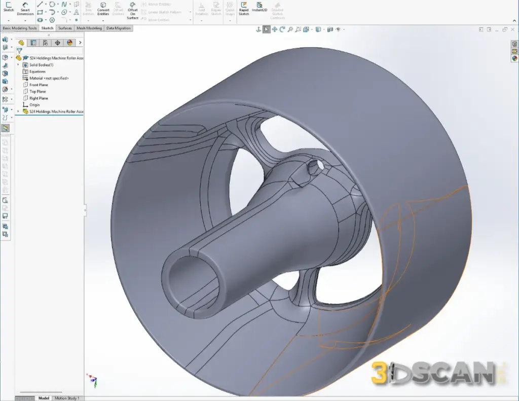
Steps Of Creating An Autosurface
The Conversion Process Explained
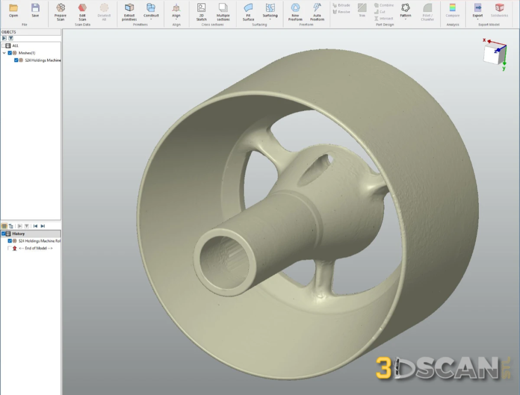
The journey from physical part to digital CAD model begins with capturing the geometry. You’ll either scan the physical part yourself using 3D scanning equipment or receive scan data from your customer. These scans arrive as mesh files—typically STL, OBJ, or PLY formats—or as point cloud data in PTX format. The raw scan data contains millions of triangles or points representing the surface of your part.
Once you have the scan data, you’ll import it into reverse engineering software designed specifically for this conversion work. The software offers two primary approaches for transforming mesh data into CAD surfaces:
-
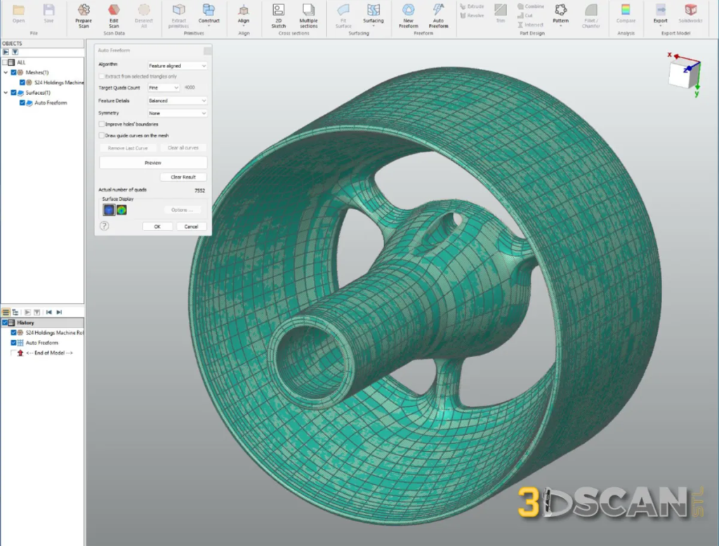
- Autosurface operates as a fully automatic method. You select regions of the mesh, and the software analyzes the geometry to generate guide curves and NURBS surfaces without manual intervention. This approach delivers fast initial results with high accuracy, though it typically produces open surface models that require additional work.
- Autosurface operates as a fully automatic method. You select regions of the mesh, and the software analyzes the geometry to generate guide curves and NURBS surfaces without manual intervention. This approach delivers fast initial results with high accuracy, though it typically produces open surface models that require additional work.
-
- Boundary Fit takes a semi-automatic approach. You manually define guide curves along the edges and key features of your scanned geometry. The software then automatically generates NURBS surfaces between these curves, creating logically structured surfaces that form closed solids more directly.
- Boundary Fit takes a semi-automatic approach. You manually define guide curves along the edges and key features of your scanned geometry. The software then automatically generates NURBS surfaces between these curves, creating logically structured surfaces that form closed solids more directly.
Both methods rely on guide curves as the foundation for surface generation. These curves define the boundaries and flow of your surfaces. The software fits NURBS surfaces to match the underlying scan data while respecting these guide curves.
Manual closing becomes necessary when your surface model contains gaps or missing surfaces. You’ll need to create additional surfaces, trim overlapping geometry, and stitch edges together to achieve a watertight solid. This step demands careful attention to ensure all surfaces connect properly without leaving any openings in your final model.
Ensuring High Accuracy and Delivering Watertight Solid Models Every Time
When you convert 3D scans to CAD solid surface models, precision matters. The target for model accuracy sits at approximately 0.05 mm average deviation between your original scan and the final CAD model. This level of measurement precision ensures you receive a reference model that faithfully represents the physical part you scanned.
You need your CAD solid models to capture the exact current state of the scanned part. This means replicating every detail, including wear patterns, manufacturing variations, and surface irregularities present on the actual component. These features aren’t flaws in the conversion—they’re essential characteristics that make your reference model valuable for quality control, reverse engineering, and design validation work.
Why Closed Solid Models Matter
You might receive open surface models from some conversion services, but these incomplete geometries create problems in your workflow:
-
- Open surfaces can’t calculate volume or mass properties
-
- CAD software struggles to perform boolean operations on incomplete models
-
- Manufacturing processes require fully enclosed geometry for toolpath generation
-
- Simulation and analysis tools need watertight surfaces to function properly
Watertight solid models eliminate these headaches. When you receive a fully closed solid model, you can immediately use it in your CAD software without spending hours manually stitching surfaces together. The conversion service handles the complex work of closing gaps, trimming overlapping surfaces, and ensuring every edge connects properly.
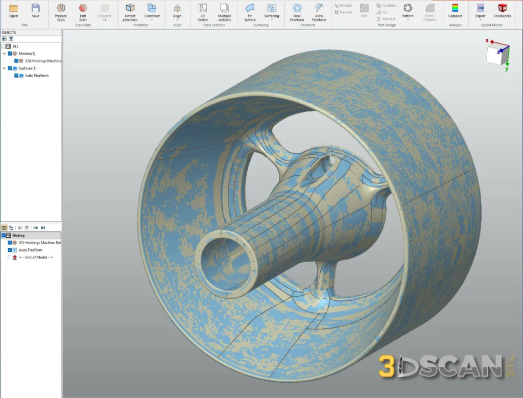
Deviation analysis accompanies each converted model, providing you with color-mapped visualizations that show exactly where and how much the CAD model differs from your original scan data. This transparency gives you confidence in the model accuracy before you integrate it into your design or manufacturing workflow
Comparing Autosurface and Boundary Fit Methods for 3D Scan to CAD Conversion
When you’re converting 3D scans to CAD solid models, you have two primary approaches available: Autosurface and Boundary Fit. Each method has its own advantages depending on your project requirements and timeline.
Autosurface Method
Autosurface delivers automatic generation of both guide curves and NURBS surfaces directly from your scan data. The software analyzes the mesh geometry and creates surfaces without requiring manual input for curve placement. This approach gives you quick results—you can generate an initial surface model in a fraction of the time compared to manual methods. The high accuracy achieved through Autosurface typically matches the scan data within tight tolerances, making it ideal when precision is your priority.
The trade-off with Autosurface is that it produces open surfaces rather than closed solids. You’ll need to invest additional time manually closing gaps and stitching surfaces together to create a watertight model. This extra step requires skill and attention to detail, but the speed of initial surface generation often compensates for the manual closure work.
Boundary Fit Method
Boundary Fit takes a different approach. You manually define guide curves along feature lines and edges of your scanned part, then the software automatically generates NURBS surfaces between these curves. This method produces logically structured surfaces that form a closed solid directly, eliminating the need for manual stitching. The surfaces follow your intended design logic, making the final model easier to edit and modify in downstream CAD operations.
Practical Applications
and Benefits for Customers
When you receive an exact current-state CAD model from a reverse engineering service, you gain a powerful tool that extends far beyond simple visualization. These converted models serve as precise digital replicas of your physical parts, enabling measurement precision that would be difficult or impossible to achieve with traditional measurement tools.
Applications in Design and Quality Control
You can use these CAD solid models as reference data within your existing design software. This means you can:
-
- Overlay new designs against the scanned part
-
- Verify clearances
-
- Check fitment
-
- Validate modifications before committing to production
Quality control teams benefit from having accurate digital representations that allow for detailed comparisons between manufactured parts and design specifications.
Importance in Manufacturing Processes
The manufacturing readiness aspect becomes critical when you need to produce replacement parts, create tooling, or integrate legacy components into new assemblies. Because the conversion process delivers watertight solid models rather than open surfaces, you can immediately use these files in:
-
- CNC programming for machining operations
-
- 3D printing preparation without additional repair work
-
- Mold design and tooling development
-
- Assembly simulations and interference checking
-
- Mass property calculations for engineering analysis
You don’t need to spend additional time closing gaps or fixing surface continuity issues. The delivered solid models are ready to import into your CAM software, send to manufacturing partners, or use as the foundation for design modifications. This immediate usability translates directly into faster project timelines and reduced engineering costs.
Additional Resources Provided with Conversion Service
When you partner with a professional conversion service to Convert 3D Scans to CAD Solid Surface Models, you receive comprehensive documentation that validates the quality and accuracy of your deliverables.
Example Data Download Packages
Example data download packages allow you to evaluate the conversion quality before committing to a full project. These sample datasets include the original scan files alongside completed CAD models created using both Autosurface and Boundary Fit methods. You can import these files into your preferred CAD software to examine the surface quality, inspect the modeling approach, and assess how well each method suits your specific requirements.
Detailed Deviation Analysis Report
Every conversion project includes a detailed deviation analysis report in PDF format. This report provides visual color maps and statistical data showing exactly how closely the final CAD model matches the original scan data. You’ll see maximum, minimum, and average deviation values, typically achieving ~0.05 mm average deviation across the entire model. These reports serve as quality certificates you can share with stakeholders or archive for compliance purposes.
Multiple File Formats for Compatibility
The converted CAD models arrive in multiple file formats STEP IGES X_T to ensure compatibility with your existing software ecosystem:
-
- STEP (.stp) – Industry-standard neutral format
-
- IGES (.igs) – Legacy system compatibility
-
- Parasolid X_T (.x_t) – Native kernel format for maximum fidelity
You receive all formats simultaneously, eliminating compatibility concerns and allowing seamless integration into your design, validation, or manufacturing workflows.
Conclusion
Now you know how we convert 3D scans to CAD solid surface models with precision and reliability. Every project we deliver includes watertight solids that integrate seamlessly into your design or manufacturing workflows—no open surfaces, no gaps, just production-ready geometry.
The choice between Autosurface and Boundary Fit depends on your specific requirements. Autosurface delivers exceptional speed and accuracy for complex organic shapes, while Boundary Fit provides logically structured surfaces ideal for parametric downstream editing. Both methods maintain the precision modeling benefits you need for quality control, reverse engineering, and product development.
Our seamless scan-to-CAD workflow transforms your physical parts into accurate digital assets you can measure, modify, and manufacture. You receive multiple file formats, comprehensive deviation analysis reports, and models that replicate the exact current state of your scanned parts.
Ready to experience the difference? Explore our sample data packages to see the quality firsthand, or reach out to discuss which conversion method aligns best with your project goals.
Frequently Asked Questions
What is 3D scan to CAD conversion and why is it important in modern manufacturing?
3D scan to CAD conversion is the process of transforming 3D scanned data, typically in STL format, into precise CAD solid surface models like STEP files. This conversion enables accurate reverse engineering, design validation, and manufacturing readiness by providing detailed digital representations of physical parts.
What is required to convert the scan into a closed surface model?
You need either a 3D scan file in mesh format (STL, OBJ, PLY) or point cloud format (PTX), along with clear conversion requirements specifying your desired accuracy level and intended use case. The scan should capture the complete geometry of your part, though missing areas can be addressed during the manual closure process.
How does the surface modeling method work in converting 3D scans to CAD models?
Surface modeling involves reconstructing scanned geometry using NURBS surfaces through reverse engineering software. Methods include automatic Autosurface generation of guide curves and surfaces, or semi-automatic Boundary Fit where guide curves are manually defined with automatic NURBS surface creation between them. Manual efforts ensure watertight, closed solid models.
What level of accuracy can be expected from 3D scan to CAD conversions?
High accuracy is achievable with average deviations around 0.05 mm between the original scan and final CAD model. This precision ensures that the CAD solid accurately replicates the current state of the physical part, including any irregularities captured during scanning.
Is deviation analysis provided to compare the original scan with the final CAD model?
Yes, deviation analysis reports in PDF format are provided as part of the conversion service. These reports quantify differences between the scanned data and the resulting CAD model to verify accuracy and quality of the conversion process.
What are the benefits of receiving a fully closed watertight solid model from 3D scan to CAD conversion?
Fully closed watertight solids ensure usability for precise measurements, quality control, reverse engineering, and manufacturing readiness. Closed solids eliminate issues associated with open surface models by providing reliable reference data ready for downstream applications in design and production workflows.