
From Scan to Solid: Turning 3D Data into Manufacturable CAD
Most 3D scan data feels like a rough draft, not a ready-to-manufacture model. You know the challenge: turning dense point clouds or messy meshes into clean, parametric CAD that engineers can trust. This post breaks down how to move from scan to CAD efficiently, sharing best practices for feature-based modeling, NURBS surfacing, and solid rebuilds—essential steps to get production-ready results in industrial reverse engineering projects.
Comprehensive Scan to CAD Workflow
The shift from scan data to reliable CAD models begins with understanding the full workflow. It involves capturing accurate data, refining it, and ensuring the end product meets all specifications.
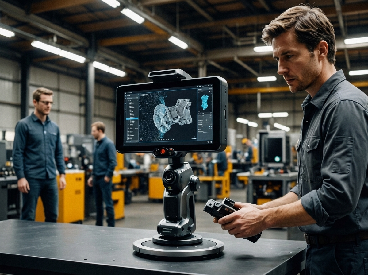
High-Accuracy 3D Scanning Techniques
Capturing precise data is the first critical step. High-accuracy 3D scanning uses advanced equipment like the Artec Ray II and Artec Leo. These tools provide exceptional detail for both small and large objects, offering a foundation for reliable models. The scanners employ laser and structured light technology to capture data with precision up to 0.02mm. This level of detail is vital for industrial applications where exact measurements are crucial.
Using the right scanner for each project ensures that the digital replica accurately reflects the physical object. This accuracy is key when you need to reverse-engineer parts or create new designs from existing components. Always consider the scale and complexity of the object when choosing a scanning technique, as different technologies offer varying levels of detail and speed.
Transforming Point Cloud to CAD Models
After scanning, the next challenge is turning point clouds into usable CAD models. This process involves cleaning and organizing data to create a coherent digital structure. Initially, you may find your point cloud dense and seemingly chaotic. The key is using software that excels in managing and simplifying this data, turning complexity into clarity.
With the right tools, point clouds become manageable. Software can help remove noise and fill gaps in the data, creating a smooth transition from scan to CAD. This transformation is crucial, especially for industries relying on precise models for manufacturing and design. You want a software solution that not only refines the data but also enhances its utility for your specific needs.
Key Considerations for Feature-Based Modeling
Once you have a clean model, feature-based modeling takes the stage. This approach focuses on defining specific features such as holes, edges, and surfaces. Feature-based modeling allows engineers to make changes easily and predictably. By focusing on these distinct elements, you ensure the CAD model remains flexible and adaptable.
Consider the materials and design constraints of your project. Feature-based modeling lets you simulate real-world conditions, addressing potential issues before they arise. For example, understanding how different materials react under stress can prevent costly errors during manufacturing. By focusing on features, you create models that are not only accurate but also practical for real-world applications.
Advanced CAD Modeling Practices
Transforming your scan data into a finished product requires advanced CAD techniques. These practices ensure that your models are not just accurate but also ready for production.
Parametric CAD and Solid Modeling Essentials
Parametric CAD offers a dynamic approach to model creation. This method uses parameters to define model attributes, making modifications straightforward. Adjusting one element can automatically update related features, saving time and reducing errors. Solid modeling, on the other hand, focuses on creating models that are as close to the end product as possible. It allows you to envision the final product in a detailed, three-dimensional form.
Both techniques are essential for industries that require precision. By using parametric and solid modeling, you maintain control over the design process, ensuring that every change is reflected accurately in the final model. This control is crucial for meeting stringent industry standards and delivering a product that meets all client specifications.
Implementing NURBS Surfacing in Projects
NURBS surfacing is a powerful tool for creating complex shapes. These surfaces provide the flexibility needed to design intricate forms with smooth curves and edges. NURBS is ideal for projects that require a high degree of detail, such as automotive and aerospace designs.
The benefit of NURBS is its ability to represent both simple geometric forms and complex organic shapes. This versatility makes it a preferred choice in industries where precision and aesthetics are both critical. By implementing NURBS, you ensure that your models are not only functional but also visually appealing, meeting both technical and design requirements.
Ensuring Production Readiness Through QA
Quality assurance is the final step in the scan-to-CAD process. It involves verifying that the model meets all necessary specifications and standards. This step is crucial to prevent costly errors during production.
A thorough QA process checks for geometric accuracy, dimensional consistency, and overall model integrity. It’s important to use both automated tools and manual inspections to catch any issues. By ensuring production readiness, you guarantee that your models are ready for manufacturing, reducing the risk of delays and additional costs.
Best Practices for Industrial Reverse Engineering
Industrial reverse engineering requires a deep understanding of both technology and industry needs. Implementing best practices can enhance your project’s success.
Effective Use of Artec Ray II and Leo Scanners
The Artec Ray II and Leo scanners are powerful tools for reverse engineering. They provide high-resolution scans that are critical for capturing detailed features of complex objects. These scanners are particularly effective for large-scale projects, such as capturing the dimensions of industrial machinery.
Using these scanners effectively involves understanding their specific capabilities and limitations. It’s important to calibrate them properly and use them in appropriate environments to ensure they deliver the best results. By mastering these tools, you can improve the accuracy and reliability of your reverse-engineered models.
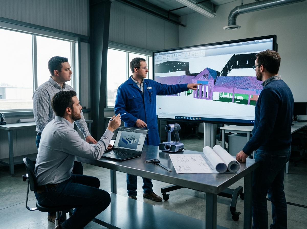
Importance of GD&T and Deviation Analysis
Geometric Dimensioning and Tolerancing (GD&T) is vital in reverse engineering. It provides a standardized method for describing the geometry of parts, ensuring that all components fit and function together as intended. Deviation analysis complements GD&T by identifying any discrepancies between the scanned model and the original design.
Both GD&T and deviation analysis are essential for quality control. They help identify potential issues early in the process, reducing the risk of defects. By incorporating these practices, you enhance your ability to produce models that meet industry standards and client expectations.
Ensuring Quality Control in Midwest 3D Scanning
Quality control is a cornerstone of 3D scanning services. In the Midwest, where industries like automotive and aerospace demand high standards, ensuring quality is paramount. This involves a combination of advanced technology and skilled technicians who understand the intricacies of each project.
By focusing on quality control, you build trust with clients. Reliable results lead to repeat business and a strong reputation in the industry. Ensuring that every scan meets the highest standards is not just a goal, but a necessity for success in the competitive world of industrial reverse engineering.